IF-CANs

IF-CAN (Intermediate Frequency CAN)

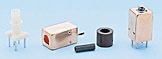
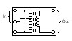
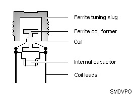
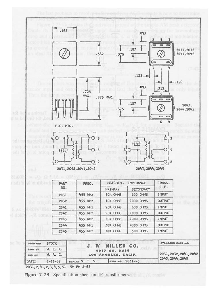
Background These transformers are specially designed tuned circuit in RFI-tight groundable metal packages for narrow bandwith IF application. They are called IF cans. As shown in the 1968 specification sheet of figure at right, this unit includes a 125-pF capacitor, and the arrow between primary and secondary indicates that the tuning is attained by tuning-tool (a non methallic screwdriver) adjustment of the ferrite core (slug). The purpose of the primary winding tap is to increase the effective Q of the collector circuit in the narrowband IF of the standard broadcast receiver. Each IF transformers has self resonans with an impedansmax at predefined frequency. The resonans frequency can be adjusted by turning the colored ferrite core. In an ordinary radio, you will most often find 4 types of IF-cans. For the FM part the IF frequency is 10.7MHz. The color of the slug in this CAN is most often pink. For the AM part the IF frequency is 455kHz.
- RED - Oscillator. With 30pf - 300pf = 1MHz to 2MHz
- YELLOW - First 455KHz IF filter transformer
- White - Second 455KHz IF filter transformer (not always used)
- Black - Last 455KHz IF filter transformer
How to connect the IF transformer? The IF use a tuned primary winding of typically 110 - 160 turns of wire with a 180pf - 200pF fitted across the coil. This winding us usually tapped at about 20 - 25% and connected to a centre pin. Unless you have any data on the coil then it is debateable from which end of the coil the tapping is made.
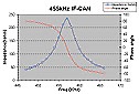
Impedance The diagram at the right shows the impedanse as function of frequeny. The phase angle is also plotted. The ferrite core (slug) is yellow 455kHz. As you can see from the diagram the Impedance has a maximum at the resonance frequency. At the resonans frequency the phase is 0 and the impedans is pure resistiv. Primary winding tap and Q-factor
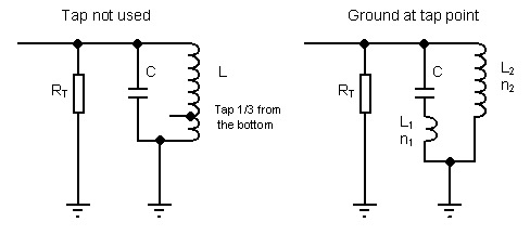
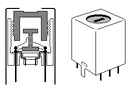
The shematic above show the IF-transformer. RT is the resistance in the amplifier stage. For instance, suppose the tap is not used.The equivalent circuit is (figure at left), of course, Qeff= RT/XL and the bandwith BW=fo/Qeff. IF the power supply line (ac ground) is connected to tap point, the resulting equivalent circuit is that of figure right. Here, L1 + L2 = L, so the circuit is resonant at the same frequency . However, since L ~ N2 ,where N is the number of turns for the inductor XL2=n2XL where n is the turns ration defined by the tap point n = n1/(n1+n2). Ignoring finite inductor Q, the effective tapped circuit Q is QT = RT / XL= RT / (n2XL) = Qeff / n2. Since n<1 ,QT> Qeff of the untapped transformer. EXAMPLE RT=2500ohm XL=500 ohm Determine the Q of the two circuits. The tap point is 1/3 of the inductor turns from the bottom. Solution Qeff=2500 / 500 = 5 XL = n2XL2 = (1/3)2*500 = 55.5 ohm. QT=2500 / 55.5 = 45. The Q has been increased by 1 / n2 = 9 times. The bandwith is 1 / 9 of the untapped value. RULE: By tapping the transformer the Q-value increase and the bandwith decrease. What is inside the CAN? The two pictures below explain the inside of the CAN.
